A cathodic protection (CP) system is only protecting your pipeline if it is working properly, and the only way to find out if it is working properly is if you test it. At a minimum, CP systems should be surveyed annually, and the rectifiers used in impressed current CP systems should be checked bi-monthly. Additional special testing may be required depending on the survey results.
What Does an Annual CP Survey Entail?
Potential Measurements
The DC pipe-to-soil potential is measured at every test station and rectifier. Potentials are measured using a high-impedance voltmeter versus a reference cell that is suitable for the environment (i.e., saturated copper/copper sulfate for soil).
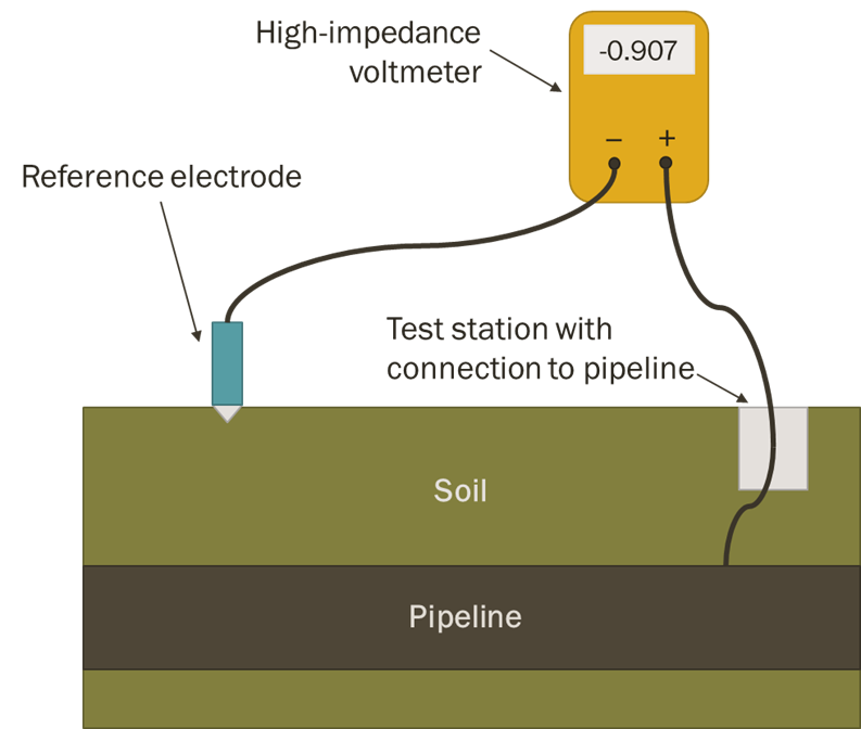
There are three types of potential measurements that are relevant:
“On” potentials are measured with the rectifier impressing current from the anodes or with the galvanic anodes connected to the pipeline. This measurement should be taken annually.
“Instant off” potentials are measured with the rectifier current output momentarily interrupted or with the galvanic anodes momentarily disconnected from the pipeline. “Instant off” potentials are measured to determine the polarized potential of the structures, as required by the AMPP (Association of Materials Protection and Performance) criteria and to eliminate “IR error” in the readings. “IR error” is due to CP current (I) flowing through the soil (R) and results in measured potentials that are greater (more electronegative) than the true potential of the structures. When the rectifier is momentarily turned off, the current flowing through the soil (I) is negligible and, therefore, the “IR error” is also negligible. This measurement should be taken annually and during the same survey as the “on” potential.
“Native” or “depolarized” potentials are measured before the CP system is energized for new systems or after the CP current source has been disconnected for an extended period of time for existing systems. This measurement should be taken every five years, at minimum.
The pipeline is considered to be protected from corrosion if at least one of the following criteria is met at each test location:
The “instant off” potential is −850 mV or more negative as measured with respect to a saturated copper/copper sulfate reference electrode.
The “native” or “depolarized” potential is at least 100 mV more negative than the “instant off” potential.
It is a best practice to protect a pipeline with the minimum amount of CP current required to adequately protect it. This approach minimizes hydrogen embrittlement, enhances coating integrity, minimizes DC stray current interference with foreign structures, and prolongs the service life of the CP system.
Potential measurements are also used to verify the effectiveness of insulating joints and casing insulators, electrical continuity, and the presence of stray currents from foreign pipeline CP systems that could lead to corrosion.

Rectifier Outputs
For annual CP surveys, the voltage and current outputs of the rectifiers are measured using a voltmeter. The voltage is measured across the output terminals of the rectifier. The current output of the rectifier is determined by measuring the voltage drop across a shunt on the rectifier panel. By knowing the voltage drop across the shunt and the resistance or calibration factor of the shunt, the current is calculated from Ohm's Law (the voltage of a circuit is equivalent to circuit current multiplied by circuit resistance, V = IR). The measured rectifier output is compared with the meters on the face of the rectifier, and the meters are adjusted, as needed. The current output of the individual anodes is determined by measuring the voltage drop across the shunts in the anode junction box. The rectifier current output can be adjusted with fine and coarse tap settings to optimize the polarization of the protected structure.

Galvanic Anode Measurements
Similar to pipe-to-soil potentials, anode open circuit potentials are measured using a voltmeter versus a reference electrode placed in contact with the soil at the test locations. The open circuit potential of an anode provides an indication of the status of the anode. The open circuit potential of an anode will shift positively over time as the anode becomes consumed.
Galvanic anode current outputs are determined in the same manner as individual impressed current anode measurements by measuring the voltage drop across the shunt. Anode current output is then determined using the resistance of the shunt and calculated with Ohm’s Law.
Close Interval Potential Survey (CIPS)
Close Interval Potential Surveys (CIPS) are done to locate areas of the pipeline that are inadequately protected between test stations and locate areas of current pickup and discharge from foreign pipeline CP systems. This survey method involves measuring the pipe-to-soil potential of the pipeline with respect to a reference electrode at approximately 5-foot intervals while the output of each rectifier is synchronized to simultaneously cycle between “on” and “off.” A wire is connected to the pipeline and strung along the alignment as the survey progresses. The pipe-to-soil potentials are recorded using a high-impedance data logging voltmeter.

AC Voltage Gradient Survey (ACVG)
ACVG surveys are done to evaluate the condition of the pipeline coating and locate coating defects, also known as “holidays.” An AC current is applied to the pipeline at accessible locations using a transmitter. The applied AC current creates a voltage gradient at holiday locations along the pipeline, which are measured using an A-Frame accessory attached to a Pipeline Current Mapper (PCM). The signal is measured across the A-Frame spikes and is displayed on the PCM in decibel (dB) microvolts. The display on the PCM shows the dB measurement and indicates the direction of the holiday using arrows. A higher dB measurement indicates the likelihood of a coating holiday location. Measurements are taken at 5-foot intervals in available soil parallel to the pipeline. This survey technique can also provide pipeline depth of cover.
AC Interference Survey
If the pipeline is near high voltage AC power lines, then an AC interference survey is conducted to evaluate the risk of AC corrosion and safety hazards. The AC pipe-to-soil potential is measured at every test station and rectifier. Potentials are measured using a high-impedance voltmeter versus a reference cell that is suitable for the environment (i.e., saturated copper/copper sulfate for soil). If present, the effectiveness of AC mitigation equipment is tested. AC mitigation equipment may include solid state decouplers, copper or zinc parallel conductors, or sacrificial anodes.
More on Corrosion Engineering and Cathodic Protection:
4 Key Factors in Estimating Cathodic Protection System Costs in Your Pipeline Project